Industrial Ultrasonic Welding Machines Guide: Process and Tooling
Industrial ultrasonic welding machines join compatible materials by applying high-frequency mechanical vibrations and controlled pressure at a defined joint.
The process creates a bond through localized heating and material deformation in thermoplastics, or through interfacial friction and plastic deformation in metals. Specialized tooling directs the energy to the required joining area.
These machines are used in automotive components, electronics, medical-device manufacturing, battery assemblies, packaging, and synthetic textiles. Successful production depends on material compatibility, joint design, tooling geometry, process parameters, and consistent quality verification.
Quick Facts About Industrial Ultrasonic Welding Machines
Feature | Description |
|---|---|
Primary purpose | Join compatible components using ultrasonic vibrations |
Main energy source | High-frequency electrical energy converted into mechanical vibration |
Common materials | Thermoplastics, selected metal combinations, synthetic fabrics and nonwovens |
Core components | Generator, transducer, booster, sonotrode, press, and fixture |
Common joining methods | Plastic welding, metal welding, spot welding, and continuous welding |
Important process variables | Amplitude, force, energy, weld time, and hold time |
Tooling requirements | Application-specific horns, anvils, nests, and fixtures |
Quality indicators | Joint strength, dimensions, appearance, and functional integrity |
Main advantage | Rapid joining without conventional filler materials in many applications |
Key limitation | Material and joint compatibility determine process suitability |
What Are Industrial Ultrasonic Welding Machines?
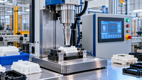
Industrial ultrasonic welding machines are production systems that use controlled mechanical vibration to create bonds between compatible materials. An ultrasonic generator supplies electrical energy to a transducer, which converts it into mechanical oscillation. A booster and sonotrode transmit that vibration to the workpieces while a press or other mechanism applies force.
For thermoplastics, localized heating softens or melts the joining surfaces, allowing the materials to fuse. For metals, high-frequency relative motion under pressure promotes intimate contact and bonding through surface disruption and plastic deformation, generally without melting the bulk materials.
Unlike conventional fusion welding, ultrasonic welding does not require the entire joint to be heated to a molten state. The process is particularly useful for repeatable assembly operations where localized energy input, short cycle times, and controlled tooling are important.
Why Industrial Ultrasonic Welding Matters
Manufacturers often need to join small components, thin materials, delicate assemblies, or parts containing heat-sensitive features. Ultrasonic welding can provide localized joining while limiting the overall thermal exposure compared with many conventional methods.
Its suitability depends on the component design and material combination rather than simply on machine power.
Production efficiency: Many ultrasonic joining cycles are short, making the process suitable for repetitive manufacturing.
Controlled energy delivery: A tuned vibration system concentrates mechanical energy at the intended joint.
Reduced consumable requirements: Many applications do not require adhesives, screws, or filler metals.
Repeatability: Programmable process settings and monitoring can support consistent production.
Compact assembly: Small joining areas can reduce the need for additional fastening features.
Automation compatibility: Ultrasonic equipment can be integrated into robotic cells and automated production lines.
Clean joining: Suitable applications can avoid adhesive residues and some of the contamination associated with alternative joining methods.
These advantages are not universal. Joint design, material compatibility, fixture stability, and process validation determine whether ultrasonic welding is appropriate.
Understanding the Ultrasonic Welding Process
Simple Explanation
Consider two compatible plastic components that need to be joined. The machine clamps the parts in a fixture, and a metal tool called a sonotrode contacts the upper component. The sonotrode vibrates at an ultrasonic frequency while applying force. Mechanical energy concentrates at the joint, softening the plastic. When vibration stops, the components remain under pressure while the joint cools and solidifies.
Metal ultrasonic welding follows a different bonding mechanism. The workpieces are clamped between a vibrating tool and a support, and controlled oscillation helps disrupt surface films and create intimate contact. The joint forms through interfacial deformation rather than conventional bulk melting.
The Role of Energy Concentration
A reliable weld requires the vibration energy to reach the intended joining interface. In plastic components, this can be achieved through joint geometry, such as an energy director, or through the shape and contact profile of the tooling.
In metal welding, the sonotrode surface, contact pressure, vibration direction, and workpiece support determine how energy is transferred to the interface. Poor energy concentration can cause weak bonds, surface damage, excessive deformation, or inconsistent results.
How Industrial Ultrasonic Welding Machines Work
Step 1: Material and Joint Preparation
The process begins with compatible materials and a joint design suited to ultrasonic energy transfer. Engineers evaluate material grade, component thickness, surface condition, joint geometry, and dimensional tolerances.
For plastic parts, joint features may concentrate energy at a defined interface. For metal parts, surface condition, overlap geometry, and clamping arrangements influence bonding. Components must be positioned consistently to reduce variation.
Step 2: Component Positioning and Clamping
The parts are placed in a nest, anvil, or fixture that supports them during welding. The fixture prevents unwanted movement and aligns the joining surfaces with the sonotrode.
Support tooling must resist the applied force and vibration without damaging the component. In automated systems, part-presence sensors or positioning mechanisms can help confirm that components are correctly located before the cycle begins.
Step 3: Ultrasonic Energy Generation
The generator converts incoming electrical power into a high-frequency electrical signal suited to the welding stack. The transducer, also called a converter, uses piezoelectric elements to transform this signal into mechanical vibration.
The operating frequency is determined by the machine and tuned stack design. Industrial equipment is available in different frequency ranges, with the appropriate choice depending on the workpiece, required amplitude, tool geometry, and production application.
Step 4: Vibration Transmission Through the Tooling
The booster transfers vibration from the transducer to the sonotrode and can increase or decrease its amplitude. The sonotrode then applies the mechanical vibration to the workpiece.
The transducer, booster, and sonotrode form a tuned assembly. Their geometry and resonance characteristics must be compatible with the generator and intended operating conditions. Incorrect assembly or unsuitable tooling can reduce energy transfer and damage components.
Step 5: Joint Formation
In thermoplastic welding, vibration produces localized heating at the interface until the joining surfaces soften or melt sufficiently to fuse. In metal welding, interfacial motion and pressure promote plastic deformation and bonding between the metal surfaces.
The amount of energy required varies with material properties, component dimensions, joint design, and tooling. A successful cycle must create sufficient bonding without causing unacceptable deformation or damage.
Step 6: Hold and Cooling
After the vibration phase, the machine maintains force for a defined hold period when required by the process. Thermoplastic joints cool and solidify under pressure, helping preserve alignment and joint integrity.
Metal welding also requires controlled process completion, although its bonding mechanism differs from plastic fusion. The appropriate force and cycle sequence depend on the specific machine and application.
Step 7: Inspection and Process Monitoring
The finished joint is checked against established quality criteria. Depending on the application, inspection may include visual examination, dimensional checks, leak testing, destructive strength testing, or functional tests.
Modern systems may monitor weld time, energy, displacement, force, or power signatures. These measurements can identify deviations, but they must be correlated with validated acceptance criteria rather than treated as automatic proof of joint strength.
Industrial Ultrasonic Welding Workflow Table
Stage | Equipment or Control | Purpose |
|---|---|---|
Part preparation | Material and joint specifications | Establish compatible joining conditions |
Positioning | Nest, anvil, or fixture | Align and support workpieces |
Energy conversion | Generator and transducer | Produce mechanical vibration |
Vibration transfer | Booster and sonotrode | Deliver vibration to the joint |
Joining | Press and controlled process settings | Form the bond |
Hold phase | Force-control mechanism | Stabilize the joint where required |
Inspection | Test equipment and monitoring controls | Verify quality |
Production recording | Machine controller or data system | Track process consistency |
Architecture and Construction of Ultrasonic Welding Equipment
Generator and Control Unit
The generator supplies the electrical signal that drives the transducer. The control unit manages process settings and may record parameters such as energy, time, displacement, and power.
Advanced controllers can use programmed limits to identify cycles that fall outside the validated process window. Integration options vary by machine and may include production-line communication and automated quality records.
Transducer or Converter
The transducer converts electrical energy into mechanical vibration through the piezoelectric effect. Its output must match the operating characteristics of the connected booster and sonotrode.
Transducers are precision components. Incorrect handling, mechanical damage, overheating, or an unsuitable resonant assembly can reduce performance and require specialist inspection.
Booster
The booster mechanically transfers vibration from the transducer to the sonotrode. Its geometry determines whether vibration amplitude is increased, reduced, or maintained.
The booster also commonly provides a mounting point for the vibration stack. Selection must account for the required amplitude, machine configuration, and resonant characteristics of the complete assembly.
Sonotrode or Welding Horn
The sonotrode is the tool that contacts the workpiece and delivers ultrasonic vibration. Its face may be flat, contoured, patterned, or designed for a particular joint.
A plastic welding horn is often designed to distribute vibration across a joining area while directing energy toward the joint interface. Metal welding horns require contact surfaces suited to the workpiece and the required vibration direction.
Press and Actuation Mechanism
The press brings the sonotrode into contact with the workpieces and applies controlled force. Actuation may be pneumatic, electric, or based on another engineered mechanism.
Force control and approach motion affect how energy enters the joint. The machine must provide repeatable movement while accommodating the component geometry and required process sequence.
Anvil, Nest, and Support Fixture
The anvil or nest holds the component opposite the sonotrode. It supports the workpiece, maintains alignment, and provides a reaction surface for the applied force.
Fixtures are often machined to match the shape of the part. Poor support can cause vibration loss, unwanted deformation, marking, or inconsistent weld quality.
Safety and Process Monitoring Controls
Machine controls may include guarded access, interlocks, emergency stops, two-hand controls where appropriate, and process alarms. The required safety measures depend on the equipment configuration and risk assessment.
Monitoring functions can help identify process variation, but they must be supported by suitable calibration, maintenance, and validated quality checks.
Main Components of Industrial Ultrasonic Welding Machines
Component | Primary Function | Important Requirement |
|---|---|---|
Ultrasonic generator | Produces the electrical drive signal | Compatibility with the tuned stack |
Transducer | Converts electrical energy into vibration | Correct operating frequency |
Booster | Transfers and modifies vibration amplitude | Suitable resonance and gain |
Sonotrode | Applies vibration to the workpiece | Correct geometry and contact surface |
Press or actuator | Applies force and controls movement | Repeatable force and displacement |
Anvil or nest | Supports and positions the workpiece | Stable, accurate alignment |
Controller | Manages welding parameters | Validated process limits |
Sensors | Monitor process conditions | Reliable measurements |
Guarding and interlocks | Reduce operator exposure to hazards | Risk-based safety design |
Types of Industrial Ultrasonic Welding Machines
Ultrasonic welding equipment can be classified by the material being joined, the way energy is applied, and the production arrangement. These categories overlap: a metal spot welder and a plastic spot welder use different joint mechanisms, while both may operate as standalone or automated systems.
Ultrasonic Plastic Welding Machines
These machines join compatible thermoplastics by generating localized heat at the interface. They are used for molded housings, appliance components, packaging parts, and selected medical-device assemblies.
Typical advantages include:
Short joining cycles for suitable component designs.
Potential for strong, repeatable joints.
No need for adhesive in many applications.
Material compatibility and joint geometry are critical. Some polymer combinations, reinforced plastics, and complex assemblies may require specialized development and testing.
Ultrasonic Metal Welding Machines
Metal ultrasonic welding equipment joins suitable metals through high-frequency relative motion and pressure. It is widely associated with electrical connections, wire splices, terminals, and selected battery-related assemblies.
Typical advantages include:
Joining without conventional bulk melting.
Suitability for selected dissimilar-metal combinations.
Potential for low electrical resistance in properly qualified electrical connections.
The process requires careful control of clamping, vibration, surface condition, and deformation. Not every metal combination or component thickness is suitable.
Ultrasonic Spot Welding Machines
Spot welding creates a localized bond at a specific point rather than along a continuous seam. The sonotrode concentrates energy in the selected area, while the fixture supports the workpiece.
Typical advantages include:
Localized joining for selected component designs.
Flexible placement of weld points.
Compatibility with automated assembly.
The joint geometry and support arrangement must prevent unwanted deformation and ensure that the vibration reaches the intended interface.
Continuous Ultrasonic Welding Machines
Continuous systems join materials along a seam or repeated path using a moving sonotrode, rotating tool, or compatible continuous-processing arrangement. They are commonly used with thermoplastic films, nonwovens, and certain textile materials.
Typical advantages include:
Integration into continuous production lines.
Seam joining and edge sealing in suitable materials.
Potential combination of joining with cutting or embossing operations.
The tooling, feed speed, material tension, and applied pressure must remain consistent to maintain seam quality.
Ultrasonic Wire Splicing and Terminal Welding Machines
These specialized systems join compatible electrical conductors or attach conductors to terminals. They are used where electrical and mechanical performance must meet defined acceptance criteria.
Typical advantages include:
Suitable joining of selected copper and aluminium conductors.
No conventional solder joint required for the ultrasonic connection itself.
Potential for automated wire-processing operations.
The equipment must be selected for conductor material, cross-sectional area, joint geometry, and electrical performance requirements. Finished connections require appropriate mechanical and electrical validation.
Ultrasonic Welding Machine Type Comparison
Machine Type | Typical Workpiece | Joining Pattern | Main Application |
|---|---|---|---|
Plastic welding machine | Thermoplastic components | Localized or defined joint | Molded parts and housings |
Metal welding machine | Compatible metal components | Overlap or localized bond | Electrical and metal assemblies |
Spot welding machine | Plastic or metal, depending on design | Discrete points | Localized component joining |
Continuous welding machine | Films, nonwovens, selected textiles | Continuous seam | Packaging and textile processing |
Wire splicing machine | Conductors and wire bundles | Compact electrical connection | Wire harnesses and electrical assemblies |
Materials and Tooling Requirements for Ultrasonic Welding
Thermoplastic Compatibility
Ultrasonic welding is generally most suitable for compatible thermoplastics. Polymer chemistry, moisture content, reinforcement, additives, component thickness, and joint geometry can all influence the result.
Similar polymer families may be easier to join than dissimilar materials, but compatibility cannot be determined from a generic material name alone. Material grades and actual component designs should be evaluated through engineering assessment and sample testing.
Metal Compatibility
Ultrasonic metal welding is commonly applied to materials such as copper, aluminium, and selected combinations used in electrical assemblies. Bond formation depends on surface films, material hardness, thickness, contact pressure, vibration direction, and tooling.
Material selection should be based on the intended mechanical and electrical requirements rather than on whether a metal can be welded in principle.
Sonotrode Materials and Construction
Sonotrodes may be manufactured from aluminium alloys, titanium alloys, or steel, depending on the application, loading, geometry, and wear requirements. No single material is optimal for every machine or process.
Tool design must account for vibration behavior, stress distribution, contact geometry, and the properties of the workpiece. Precision machining and appropriate inspection are important because tool defects can affect both performance and service life.
Joint Design and Energy Directors
For plastic parts, energy directors are features designed to concentrate vibration energy at the joint. Other joint arrangements use stepped, shear, or related geometries, depending on the component and sealing requirements.
In metal welding, contact geometry and clamping arrangement influence how vibration is transferred through the interface. Tooling must provide sufficient support without obstructing the required relative motion.
Fixture Design and Part Positioning
Fixtures should locate the parts consistently and support them near the joining area. A fixture that is too flexible can absorb energy or allow movement, while unsuitable contact surfaces may mark or damage the workpiece.
For production equipment, fixture repeatability should be considered alongside changeover requirements, part tolerances, and automated loading.
Tooling Maintenance and Replacement
Tooling condition affects energy transfer and joint consistency. Inspection should cover cracks, wear, mounting surfaces, fasteners, contact-face damage, and alignment.
Replacement tooling must match the machine's frequency and mechanical requirements. A horn should not be modified or interchanged casually because changes in geometry can alter its resonance and stress distribution.
Ultrasonic Welding vs. Other Joining Methods
Ultrasonic welding is one of several methods available for assembling plastics, metals, and flexible materials. The most appropriate method depends on joint accessibility, material compatibility, strength requirements, sealing needs, production volume, and inspection requirements.
Feature | Ultrasonic Welding | Heat Staking | Adhesive Bonding | Conventional Fusion Welding |
|---|---|---|---|---|
Main mechanism | Mechanical vibration and localized bonding | Localized heating and deformation | Chemical or physical adhesion | Melting and fusion, depending on process |
Typical materials | Compatible thermoplastics and selected metals | Mainly thermoplastic features | Broad range, depending on adhesive | Suitable weldable metals and some plastics |
Joining cycle | Often short | Depends on heating and cooling | Includes application and curing requirements | Varies by welding method |
Added material | Often not required | Not usually required | Adhesive is required | Filler may or may not be required |
Tooling needs | Tuned horn and supporting fixture | Heated tool and support fixture | Application equipment and surface preparation | Welding equipment and appropriate fixtures |
Main limitation | Material and joint sensitivity | Requires suitable deformable features | Curing, contamination, and aging considerations | Heat effects and process-specific requirements |
Ultrasonic welding should not automatically replace another joining method. A qualified comparison should consider total production requirements, joint performance, process validation, maintenance, and the consequences of a failed joint.
Benefits and Advantages of Industrial Ultrasonic Welding Machines
Industrial ultrasonic welding machines provide a combination of speed, controlled energy delivery, and automation potential. Their value is greatest when the workpiece and joint are specifically designed for the process.
Short cycle times: Many suitable plastic joining operations can be completed rapidly.
Repeatable joining: Programmed parameters help maintain consistency when materials, tooling, and parts remain controlled.
Localized energy input: Vibration concentrates energy near the joint rather than heating the entire component.
Reduced consumables: Many processes do not require adhesives, screws, or filler materials.
Compact equipment integration: Welding heads can be incorporated into automated workstations.
Process monitoring: Controllers can record operating parameters and identify cycles outside defined limits.
Clean assembly: Suitable applications can avoid adhesive residue and associated curing operations.
Flexible tooling: Application-specific horns and fixtures support different component geometries.
The realized benefits depend on correct process development. Tooling wear, material variation, poor positioning, and incorrect parameters can undermine consistency even when the machine itself is capable of repeatable operation.
Industry Applications of Industrial Ultrasonic Welding Machines
Automotive Manufacturing
Ultrasonic welding is used for suitable interior components, lighting assemblies, sensor housings, wire connections, and selected electrical assemblies. The process can support repeatable joining in high-volume production, provided the materials and component geometry meet the required performance criteria.
Automotive applications may involve both plastic welding and metal conductor joining. Each requires a separate process specification and appropriate validation.
Electronics Manufacturing
Electronic assemblies can contain small plastic housings, connectors, wire bundles, and delicate internal components. Ultrasonic welding supports selected enclosure and conductor-joining operations where localized energy delivery is advantageous.
Tooling must prevent damage to nearby components, and quality testing should address the specific electrical, mechanical, and environmental requirements of the assembly.
Battery and Electrical Connection Manufacturing
Ultrasonic metal welding is used for selected conductor splices, electrical terminals, and battery-related connections. Copper and aluminium components may be joined in suitable configurations.
These joints require careful validation because resistance, mechanical strength, thermal behavior, and long-term stability can affect the performance of the electrical assembly.
Medical Device Manufacturing
Selected medical-device housings, fluid-handling components, and compatible thermoplastic assemblies can be joined using ultrasonic welding. The method may support controlled assembly without introducing adhesive into the joint.
Applications involving sterile barriers, fluid integrity, or critical device performance require documented process validation, suitable material controls, and application-specific testing.
Packaging Manufacturing
Ultrasonic technology is used to seal selected thermoplastic films and nonwoven materials. Continuous equipment can support seam formation, edge sealing, and integrated cutting operations in compatible packaging processes.
The required seal strength and integrity depend on the packaging material, contamination conditions, tooling pattern, and process settings.
Textile and Nonwoven Manufacturing
Synthetic textiles and nonwoven materials can be bonded, cut, or embossed using ultrasonic equipment. Applications include selected filtration materials, hygiene products, technical textiles, and synthetic fabric assemblies.
Fiber composition, material orientation, thickness, and feed conditions influence the quality of the resulting seam or edge.
Appliance and Consumer Product Manufacturing
Ultrasonic plastic welding can join selected housings, covers, internal supports, and molded assemblies used in appliances and consumer products. It is particularly useful where a compact joint and repeatable production cycle are required.
Component designers must account for visible surface marking, joint accessibility, internal features, and dimensional tolerances.
Industry Applications Table for Ultrasonic Welding
Industry | Typical Components | Common Process | Main Quality Concern |
|---|---|---|---|
Automotive | Plastic housings and wire connections | Plastic or metal welding | Mechanical integrity and durability |
Electronics | Connectors and enclosures | Plastic welding or wire splicing | Electrical performance and component protection |
Battery manufacturing | Conductors and selected terminals | Metal welding | Resistance and joint consistency |
Medical devices | Compatible housings and fluid components | Plastic welding | Integrity and process validation |
Packaging | Films and nonwoven structures | Continuous welding | Seal strength and leak integrity |
Textiles | Synthetic fabrics and nonwovens | Continuous welding or bonding | Seam consistency |
Appliances | Molded housings and supports | Plastic welding | Joint strength and appearance |
Industrial Ultrasonic Welding Standards and Safety
Standards and safety requirements depend on the material, intended application, machine design, and market in which the equipment operates. A standard covering a particular connection type should not be treated as a universal certification for every ultrasonic welding machine.
ISO 23512:2021
ISO 23512:2021, Plastics — Joining of thermoplastic moulded components — Specification of variables for thermal joining processes, addresses essential process variables for specified joining methods, including ultrasonic welding, staking, and spot welding.
It provides a framework for documenting and controlling relevant variables so that the required component quality can be achieved consistently.
IEC 60352-9:2024
IEC 60352-9:2024, Solderless connections — Part 9: Ultrasonically welded connections — General requirements, test methods and practical guidance, addresses ultrasonically welded electrical connections involving specified copper, copper-alloy, aluminium, and aluminium-alloy conductors.
Its applicability should be checked against the actual connection type and requirements of the electrical assembly.
Machine Safety and Operator Protection
Industrial ultrasonic welding equipment presents mechanical, electrical, acoustic, and process-specific hazards. Moving presses can create pinch points, and some systems can generate audible or ultrasonic noise that requires assessment.
Appropriate safeguards may include:
Guards and interlocked access points.
Emergency-stop arrangements.
Suitable operator controls and safe loading procedures.
Noise assessment and hearing protection where required.
Electrical isolation before maintenance.
Training for tooling changes and machine operation.
High-power ultrasound equipment should be assessed for airborne sound and contact-related hazards. Operators should not bypass guarding or handle a vibrating tool while the system is energized.
Common Ultrasonic Welding Challenges and Solutions
Challenge | Possible Cause | Appropriate Response |
|---|---|---|
Weak weld joint | Insufficient energy transfer or unsuitable joint design | Review material compatibility, joint geometry, and validated settings |
Excessive deformation | Excessive energy, force, or unsuitable tooling | Evaluate displacement, force, and horn contact |
Inconsistent weld quality | Part variation, fixture movement, or unstable parameters | Improve positioning and monitor process variables |
Surface marking | Excessive local pressure or unsuitable horn face | Review contact geometry and force distribution |
Horn cracking | Excessive stress, incorrect resonance, or tooling damage | Arrange specialist inspection and verify stack compatibility |
Poor energy transfer | Incorrect stack assembly or inadequate support | Check mounting, resonance, and fixture stability |
Incomplete plastic fusion | Unsuitable polymer combination or insufficient joint heating | Review material grade and joint design |
Unstable metal connections | Variable surface condition, force, or vibration | Validate the material preparation and welding process |
Excessive flash or material displacement | Incorrect joint geometry or excessive energy | Optimize the process within validated limits |
Tooling wear | Abrasion, high loading, or unsuitable tool material | Inspect contact surfaces and review tooling selection |
Changes to frequency, amplitude, force, energy, or tool geometry should be made through controlled process development. Random adjustments can improve one quality indicator while worsening another.
How to Choose an Industrial Ultrasonic Welding Machine
Selecting an industrial ultrasonic welding machine begins with defining the workpiece and the required joint. A machine that is suitable for thin plastic housings may not be suitable for metal conductor splicing or continuous film sealing.
Selection Factor | What to Evaluate | Why It Matters |
|---|---|---|
Material type | Polymer grade, metal composition, or textile structure | Establishes process compatibility |
Component geometry | Joint area, thickness, shape, and access | Determines tooling and energy transfer |
Joining method | Plastic fusion, metal bonding, spot welding, or continuous welding | Defines the machine configuration |
Frequency and amplitude | Required vibration characteristics | Influences energy transfer and tool design |
Force and displacement | Required clamping and movement control | Affects joint formation |
Generator capability | Power delivery and process control | Must match the application and tuned stack |
Tooling requirements | Horn, booster, anvil, and fixture design | Influences weld quality and repeatability |
Production volume | Manual, semi-automatic, or automated operation | Determines handling and integration needs |
Quality requirements | Strength, electrical resistance, leak integrity, or appearance | Defines validation and inspection |
Traceability | Data recording and cycle monitoring | Supports process control |
Maintenance support | Tool inspection, replacement, and technical expertise | Affects long-term operating reliability |
Safety requirements | Guarding, noise, and application-specific hazards | Protects operators and equipment |
Manual and Benchtop Equipment
Benchtop machines are suitable for laboratory development, sample evaluation, small production runs, and applications where an operator loads each part. They can provide a practical way to assess material compatibility and establish initial process parameters.
Their suitability depends on the required force, workpiece size, tooling, and process control features. A compact machine should not be assumed capable of meeting every industrial duty requirement.
Automated Production Systems
Automated ultrasonic welding systems are appropriate for repetitive operations requiring controlled loading, consistent positioning, cycle monitoring, and integration with production equipment.
The design may include part-presence sensors, robotic handling, automated fixtures, and data collection. The full system should be assessed for cycle consistency, maintainability, changeover requirements, and safe access.
Application-Specific Tooling Systems
Some applications require custom sonotrodes, nests, and fixtures rather than standard tooling. Complex component shapes, multiple weld points, delicate surfaces, and tight dimensional tolerances can make tooling design a major part of process development.
Before production, sample parts should be used to establish whether the proposed tooling delivers acceptable results across the expected operating range.
Maintenance Best Practices for Ultrasonic Welding Equipment
Routine maintenance protects the vibration stack, tooling, actuator, and control system. Maintenance intervals should follow the equipment manufacturer's instructions, operating conditions, and observed wear rather than a universal schedule.
Inspect the Sonotrode and Fixture
Check the sonotrode face, mounting surfaces, fixture contacts, and alignment for wear, cracks, looseness, or damage. Even small changes in contact geometry can alter energy transfer and weld consistency.
Tool replacement or re-machining should preserve the design and resonance requirements of the assembly.
Check the Vibration Stack
The transducer, booster, and sonotrode must remain compatible and correctly assembled. Inspect mounting interfaces and follow the specified procedures for tightening and handling components.
Damaged or improperly assembled stack components should be assessed by qualified personnel before the machine returns to production.
Monitor Process Data
Review trends in weld time, energy, force, displacement, and power where these measurements are available. Changes from the validated process baseline may indicate tooling wear, material variation, or a developing machine fault.
Monitoring limits should be based on demonstrated relationships between process measurements and finished-joint quality.
Maintain the Actuator and Mechanical System
Inspect the press mechanism, guides, drive system, sensors, and moving parts according to the maintenance plan. Verify that the sonotrode approaches the workpiece consistently and that the force-control mechanism operates correctly.
Unexpected movement, vibration, or noise should be investigated before normal production continues.
Verify Electrical and Safety Controls
Inspect cables, connectors, grounding arrangements, guards, interlocks, and emergency-stop functions according to the manufacturer's procedures. Electrical isolation is necessary before maintenance that exposes hazardous electrical or moving components.
Document Tooling Changes and Repairs
Record tool identification, maintenance work, process changes, inspection results, and relevant quality findings. Traceable records help distinguish material-related defects from machine, tooling, or process problems.
Limitations of Industrial Ultrasonic Welding Machines
Ultrasonic welding offers substantial advantages for suitable applications, but it is not a universal joining method.
Material restrictions: Not all polymers, metals, or mixed-material combinations can form acceptable ultrasonic joints.
Joint geometry sensitivity: Energy must reach the intended interface, making component design important.
Tooling complexity: Specialized horns and fixtures can require significant engineering and precision manufacturing.
Component constraints: Part thickness, size, stiffness, and accessibility can limit feasibility.
Surface and appearance effects: Localized pressure and vibration may leave marks or cause deformation.
Process sensitivity: Material variation and changes in force, amplitude, energy, or positioning can affect the result.
Equipment compatibility: The generator and tuned vibration stack must be matched correctly.
Validation requirements: Critical joints may require destructive tests, electrical measurements, leak tests, or other application-specific verification.
Maintenance demands: Tool wear and stack damage can interrupt production or reduce joint quality.
A feasibility study using representative parts is often necessary before committing to tooling and production integration, particularly for safety-critical, electrical, or sealed assemblies.
Future Trends in Industrial Ultrasonic Welding Technology
Closed-Loop Process Control
Newer control approaches can monitor vibration and joining behavior during each cycle. Where supported by the equipment, feedback can help maintain defined process conditions and identify abnormal welds.
Digital Production Monitoring
Machine data can be integrated with manufacturing records to improve traceability, analyze cycle variation, and support maintenance planning. Data collection is most useful when measurements are linked to validated quality criteria.
More Precise Tooling Design
Computer-aided engineering and vibration analysis can support the development of sonotrodes and fixtures that distribute energy more consistently. Tooling still requires practical verification because material behavior and actual contact conditions influence performance.
Battery and Electrical Assembly Applications
Ultrasonic metal welding continues to be relevant to selected electrical connections and battery-related assemblies. These applications require careful attention to joint resistance, mechanical strength, repeatability, and long-term performance.
Flexible Automation
Integration with robots, automated handling, and configurable fixtures can support different part geometries and production sequences. Successful integration depends on maintaining accurate positioning, appropriate process control, and safe machine access.
Frequently Asked Questions About Industrial Ultrasonic Welding Machines
1. What is an industrial ultrasonic welding machine?
An industrial ultrasonic welding machine uses high-frequency mechanical vibration and controlled force to join compatible materials. It includes a generator, transducer, vibration stack, sonotrode, and supporting tooling, with configurations tailored to the joining application.
2. How does ultrasonic plastic welding work?
The machine presses compatible thermoplastic components together and applies ultrasonic vibration at their joint. Localized heating softens or melts the joining surfaces, and the parts are held under pressure as the joint solidifies.
3. Can ultrasonic welding join metals?
Yes. Ultrasonic metal welding is used for suitable metals, particularly selected copper and aluminium conductors and electrical connections. Bond formation generally relies on interfacial motion and plastic deformation rather than conventional bulk melting.
4. What is the difference between a sonotrode and a booster?
The booster transfers vibration from the transducer and changes its amplitude according to its design. The sonotrode, also called the welding horn, contacts the workpiece and directs vibration into the joining area.
5. Which materials are suitable for ultrasonic welding?
Compatible thermoplastics, selected metals, and certain synthetic textiles or nonwovens can be joined using appropriate ultrasonic processes. Suitability depends on the material grade, component design, surface condition, and required joint performance.
6. What factors affect ultrasonic weld quality?
Important factors include amplitude, applied force, weld time, energy input, joint geometry, material compatibility, and fixture stability. Tooling condition and material variation can also affect repeatability.
7. Does ultrasonic welding require adhesives or filler materials?
Many ultrasonic welding applications do not require adhesives or filler materials because the bond forms directly between compatible workpieces. Whether additional materials are needed depends on the specific assembly design and any supplementary process requirements.
8. What is the purpose of ultrasonic welding tooling?
Tooling positions and supports the workpieces while directing vibration into the joint. The sonotrode, booster, anvil, and fixture must be compatible with the machine and application to achieve repeatable joining results.
9. How is ultrasonic weld quality tested?
Testing may include visual inspection, dimensional checks, destructive strength tests, electrical resistance measurements, or leak testing, depending on the application. Machine monitoring data can support quality control but should be correlated with validated acceptance criteria.
10. Is ultrasonic welding suitable for automated production?
Yes. Ultrasonic welding can be integrated into automated production lines using controlled presses, part-positioning fixtures, sensors, and robotic handling. The system must be validated for cycle consistency, product quality, and operator safety.
Conclusion
Industrial ultrasonic welding machines join compatible plastics, metals, and selected flexible materials through controlled mechanical vibration and application-specific tooling. Their performance depends on material compatibility, joint geometry, tuned vibration components, force control, and validated process settings. Careful machine selection, tooling maintenance, safety measures, and quality testing help manufacturers achieve repeatable joints suited to their production requirements.

Related Post...
Industrial 3D Printing Materials: Selection Guide and Properties
Updated: October 24, 2026
Read More