PLC Control Systems: Fundamentals, Architecture, Programming & Applications
Programmable Logic Controllers (PLCs) are specialized industrial computers used to monitor equipment, process input signals, and control machinery through programmed instructions. They are widely used in manufacturing plants, power generation facilities, water treatment systems, packaging operations, and other industrial environments.
Unlike general-purpose computers, PLCs are designed to operate reliably in demanding conditions, including electrical noise, temperature variations, vibration, and continuous operation.
A PLC receives information from connected devices such as sensors, switches, and measurement instruments. It processes this information according to a stored program and sends output signals to devices such as motors, valves, pumps, and alarms.
Understanding PLC control systems involves examining their basic functions, hardware components, system architecture, programming methods, and practical applications.
What Is a Programmable Logic Controller?
A Programmable Logic Controller is a digital control device designed to automate industrial processes. It uses a user-defined program to determine how connected equipment should respond to different input conditions.
For example, in an automated packaging line, a PLC can receive a signal from a sensor when a product reaches a particular position. It can then activate a conveyor, operate a filling mechanism, or control a packaging operation according to the programmed sequence.
PLCs are commonly used for:
Controlling industrial machinery and production lines.
Monitoring temperature, pressure, flow, and level.
Operating pumps, motors, and conveyor systems.
Managing automated assembly processes.
Controlling safety-related functions through appropriately designed safety systems.
Recording operating conditions and communicating with supervisory systems.
Fundamentals of PLC Working Principles
A PLC generally follows a repeated operating process known as the scan cycle. During this cycle, it reads input information, executes the control program, and updates its outputs.
1. Input Reading
The PLC receives signals from field devices connected to its input modules. These devices may include proximity sensors, push buttons, limit switches, temperature transmitters, and pressure sensors.
Inputs can be digital or analog.
Digital inputs represent two states, such as ON and OFF.
Analog inputs represent continuously varying measurements, such as temperature, pressure, or flow.
2. Program Execution
The processor evaluates the input information according to the instructions stored in its memory.
For example, a program may specify that a motor should start when a start button is pressed and stop when a stop button is activated.
3. Output Updating
After executing the program, the PLC updates its output modules. These modules send signals to connected devices such as contactors, indicator lamps, solenoid valves, and motor drives.
4. Repeating the Scan Cycle
The PLC continuously repeats this process while operating. The time required for one complete cycle is known as scan time.
Scan time depends on factors such as program size, processor performance, communication tasks, and the complexity of the control system.
PLC System Architecture
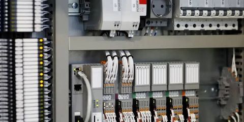
A PLC system consists of multiple hardware and software elements that work together to control industrial equipment. Its architecture can be expanded according to the size and requirements of an application.
<PRIVATE_PERSON>### Main Components of a PLC System
| Component | Function |
|---|---|
| Central Processing Unit (CPU) | Executes the control program and manages system operations. |
| Power Supply | Provides the required electrical power to the PLC hardware. |
| Input Modules | Receive signals from sensors, switches, and measurement devices. |
| Output Modules | Send control signals to motors, valves, relays, and other equipment. |
| Memory | Stores programs, configuration data, and operating information. |
| Communication Interface | Connects the PLC with other controllers, computers, and industrial networks. |
| Programming Device | Allows engineers to create, test, monitor, and modify PLC programs. |
| Rack or Backplane | Provides mechanical support and electrical connections between compatible modules. |
Central Processing Unit
The CPU is the main processing component of a PLC. It executes the control instructions, processes input data, manages outputs, and coordinates communication with other system components.
Different PLC models have different processing capabilities, memory capacities, and supported communication options.
Input and Output Modules
Input and output modules provide the connection between the PLC and the industrial environment.
Digital input modules receive signals from devices such as switches and sensors. Digital output modules control devices that operate through discrete signals.
Analog modules handle variable signals from instruments. For example, an analog input module may receive a signal from a pressure transmitter and convert it into a digital value that the PLC can process.
PLC Memory
PLC memory stores the operating program and relevant system information. Depending on the controller, memory may include program storage, working memory, data registers, and retentive areas.
Retentive memory can preserve selected information after a power interruption, depending on the PLC configuration and memory technology.
Communication Interfaces
Communication interfaces allow PLCs to exchange information with other industrial devices. Common communication technologies include:
Ethernet-based industrial communication.
Modbus RTU and Modbus TCP.
PROFINET.
EtherNet/IP.
PROFIBUS.
Serial communication interfaces.
The appropriate protocol depends on device compatibility, network design, response requirements, and application needs.
Types of PLC Systems
PLCs are available in different physical configurations and processing capacities. The selection depends on the number of inputs and outputs, control complexity, expansion requirements, and operating environment.
Compact PLC
<PRIVATE_PERSON>Compact PLCs combine the CPU, power supply, and a fixed or limited number of input and output points in one unit.
They are commonly used in smaller automation applications, such as individual machines, small pumping stations, and basic production equipment.
Modular PLC
Modular PLCs use separate hardware modules that can be installed in a compatible rack or base unit.
This architecture allows users to select CPU, communication, digital input, digital output, and analog modules according to system requirements.
Rack-Mounted PLC
Rack-mounted PLC systems use a larger hardware structure that can accommodate multiple modules. They are suitable for complex industrial applications requiring numerous inputs, outputs, communication interfaces, and expansion options.
Safety PLC
Safety PLCs are designed for safety-related control functions. They are developed and certified for specific safety applications and are used with compatible safety devices and engineering practices.
Examples include emergency-stop systems, safety interlocks, and machine guarding applications. Their design must follow applicable functional safety requirements.
PLC Programming Languages
PLC programming languages allow engineers to create instructions that control industrial processes. The IEC 61131-3 standard defines several programming language approaches commonly used in industrial automation.
1. Ladder Diagram (LD)
<PRIVATE_PERSON>Ladder Diagram is a graphical programming language that represents control logic using symbols arranged in horizontal rungs.
Its appearance is similar to traditional electrical relay circuits. It is widely used for motor control, interlocking, machine sequencing, and basic automation tasks.
2. Function Block Diagram (FBD)
Function Block Diagram uses interconnected blocks to represent control functions. Each block performs a particular operation, such as timing, counting, comparison, or mathematical processing.
FBD is useful when developing systems that involve multiple connected functions and signal-processing operations.
3. Structured Text (ST)
Structured Text is a high-level textual programming language used for complex control logic, mathematical calculations, data handling, and conditional operations.
It supports programming structures such as IF statements, loops, and variable assignments.
4. Sequential Function Chart (SFC)
Sequential Function Chart represents a process through steps and transitions. It is useful for applications that follow a defined operating sequence.
For example, an automated filling machine may perform container detection, positioning, filling, and release in a specific order.
5. Instruction List (IL)
Instruction List is a low-level textual language that was included in earlier editions of IEC 61131-3. It has been deprecated in newer editions of the standard, so support depends on the software and controller being used.
PLC Programming Example: Motor Start and Stop
A simple motor control application helps explain how PLC programming works.
Consider a conveyor motor that needs to start when an operator presses a start button and stop when the stop button is pressed.
The basic control requirements are:
A start push button provides the start command.
A stop push button provides the stop command.
A motor contactor controls the motor's power circuit.
The PLC processes the commands and controls the contactor output.
In a typical ladder logic arrangement, a seal-in or holding contact maintains the motor command after the start button is released. Pressing the stop button breaks the control condition and deactivates the output.
This is a simplified educational example. Actual motor-control installations require correctly designed electrical protection, suitable interlocks, and appropriate safety arrangements. Emergency-stop functions should not depend solely on ordinary PLC logic.
PLC Applications in Industrial Automation
PLCs are used across a wide range of industries because they can control repetitive processes, monitor equipment, and coordinate automated operations.
<PRIVATE_PERSON>### Manufacturing and Assembly Lines
In manufacturing facilities, PLCs coordinate conveyor belts, robotic equipment, assembly stations, and production machinery.
They help maintain operating sequences and support consistent machine operations.
Packaging and Material Handling
Packaging systems use PLCs to control filling, sealing, labeling, sorting, and product movement.
Sensors provide information about product position, while the PLC coordinates the actions of connected equipment.
Water and Wastewater Treatment
PLCs monitor and control pumps, valves, tanks, and treatment equipment.
They can use measurements such as water level, pressure, and flow to manage pumping operations and treatment sequences.
Food and Beverage Processing
Food processing facilities use PLCs to control mixing, heating, cooling, filling, and packaging operations.
Control systems can also support temperature monitoring and process timing. Hygiene requirements and equipment design remain important considerations.
Power Generation and Energy Systems
PLCs can support auxiliary equipment control, cooling systems, pump operations, and monitoring functions in energy facilities.
The specific control architecture depends on the plant's operational and safety requirements.
Building Automation
PLCs and other programmable controllers can be used to manage ventilation equipment, pumps, lighting sequences, and selected building infrastructure functions.
PLCs and SCADA Systems
PLCs and Supervisory Control and Data Acquisition (SCADA) systems often work together in industrial automation.
A PLC performs local control tasks by processing signals and operating connected equipment. A SCADA system provides a higher-level interface for monitoring, data collection, alarms, and supervisory operations.
| Feature | PLC | SCADA |
|---|---|---|
| Primary Role | Local machine and process control | Supervisory monitoring and data acquisition |
| Main Function | Executes control logic | Displays process information and system status |
| Typical Interface | Sensors, actuators, and field devices | PLCs, remote terminal units, and industrial networks |
| Operation | Executes control programs | Provides operator screens, alarms, and historical information |
| Application | Machine and equipment automation | Plant-wide or geographically distributed monitoring |
A SCADA system does not necessarily replace a PLC. Instead, the two technologies commonly complement each other.
Advantages of PLC Control Systems
PLCs provide several benefits in industrial automation when selected and configured appropriately.
Reliable operation: Industrial PLCs are designed for demanding operating environments.
Flexible programming: Control logic can be modified to accommodate process changes.
Reduced wiring complexity: Many control functions can be implemented through software rather than extensive relay-based arrangements.
Fast control response: PLCs can process inputs and update outputs within defined scan and response times.
System expansion: Modular controllers can support additional modules when compatible hardware is available.
Fault identification: Diagnostic functions can help engineers investigate communication, module, and program-related issues.
Integration: PLCs can communicate with compatible drives, HMIs, SCADA platforms, and other automation equipment.
Common PLC Challenges and Limitations
Although PLCs are widely used, their implementation involves technical and operational considerations.
Hardware Compatibility
Not all PLC modules, programming software, or communication devices are compatible with one another. Hardware selection should consider the controller family, supported protocols, electrical ratings, and expansion requirements.
Programming Complexity
Complex automation systems may require advanced programming knowledge, testing, documentation, and careful management of program changes.
Maintenance Requirements
PLCs require periodic inspection of electrical connections, power supplies, communication networks, backup systems, and operating conditions.
Cybersecurity Risks
Network-connected PLCs may be exposed to cybersecurity threats if access controls, network segmentation, and security updates are not properly managed.
Industrial control systems should be designed with appropriate cybersecurity measures and controlled access to programming and operating environments.
Dependence on Power and Network Infrastructure
A power interruption or communication failure can affect system operation. Appropriate power protection, backup arrangements, and recovery procedures should be considered during system design.
PLC Maintenance and Troubleshooting
Regular maintenance helps identify developing issues and supports reliable operation.
Common maintenance activities include:
Inspecting electrical connections and terminal blocks.
Checking power supply output and module status indicators.
Reviewing PLC diagnostic messages and fault logs.
Inspecting communication cables and network connections.
Checking sensor readings and actuator responses.
Maintaining current backups of PLC programs and configurations.
Reviewing cabinet ventilation, temperature, dust, and moisture conditions.
Testing control sequences according to approved maintenance procedures.
Common PLC-related problems include input signal failures, output module faults, incorrect program conditions, communication errors, and power supply issues.
Before troubleshooting, technicians should follow appropriate electrical isolation and lockout procedures. Changes to live industrial control systems should only be performed by qualified personnel under approved procedures.
Factors to Consider When Selecting a PLC
Choosing a PLC requires an understanding of the process, equipment, and future expansion requirements.
| Selection Factor | What to Evaluate |
|---|---|
| Input and Output Capacity | Number and type of connected sensors and actuators. |
| Processing Performance | Program complexity and required response time. |
| Memory Capacity | Program size and data-storage requirements. |
| Communication Support | Required industrial protocols and network interfaces. |
| Expansion Capability | Availability of compatible additional modules. |
| Environmental Conditions | Temperature, vibration, dust, moisture, and electrical noise. |
| Safety Requirements | Whether a certified safety controller or separate safety system is required. |
| Programming Software | Compatibility, engineering tools, and long-term support. |
A suitable PLC should meet current operating requirements while allowing reasonable flexibility for future system modifications.
Frequently Asked Questions
1. What is the main purpose of a PLC?
The main purpose of a PLC is to automate industrial equipment and processes by receiving input signals, executing programmed instructions, and controlling output devices.
2. What are the main components of a PLC?
The main components include the CPU, power supply, memory, input modules, output modules, communication interfaces, and programming device.
3. Which programming language is commonly used in PLCs?
Ladder Diagram is widely used because its graphical structure resembles traditional electrical relay circuits. Other common IEC 61131-3 languages include Function Block Diagram and Structured Text.
4. What is the difference between a PLC and a SCADA system?
A PLC performs local control operations, while SCADA provides supervisory monitoring, data collection, alarms, and operator interfaces. They often work together.
5. Where are PLC control systems used?
PLCs are used in manufacturing, packaging, water treatment, food processing, energy facilities, material handling, and building automation.
6. What is a PLC scan cycle?
A PLC scan cycle is the repeated process of reading input information, executing the stored program, and updating output signals.
Conclusion
PLC control systems are an important part of modern industrial automation. Their ability to process signals, execute programmed instructions, and control connected equipment makes them useful across manufacturing, processing, utilities, and infrastructure operations.
Understanding PLC architecture, programming languages, scan cycles, communication methods, and maintenance requirements provides a foundation for working with industrial control systems. Proper hardware selection, documented programming, electrical protection, cybersecurity, and safety engineering are essential for dependable system operation.
Disclaimer: This article is intended for general educational and informational purposes. Actual PLC installation, programming, electrical work, and safety-system design should be carried out by qualified professionals in accordance with applicable standards, manufacturer documentation, and site-specific requirements.

Related Post...
Hydraulic Power Systems: Fundamentals, Component, and Practical Knowledge
Updated: November 03, 2026
Read More
Pneumatic Power Systems: Fundamentals, Components & Practical Knowledge
Updated: November 12, 2026
Read More